Local master: /Users/forgebot/outputs/valve-texturing-test/index.html
EXPERIMENTAL RESULT · PARTIAL REFERENCE MATCH
Valve Assembly: The Texturing Test
Ten illustrated steps, including the failed first pass. The model is real, the maps are new, and the original textured asset was not used.
What went well
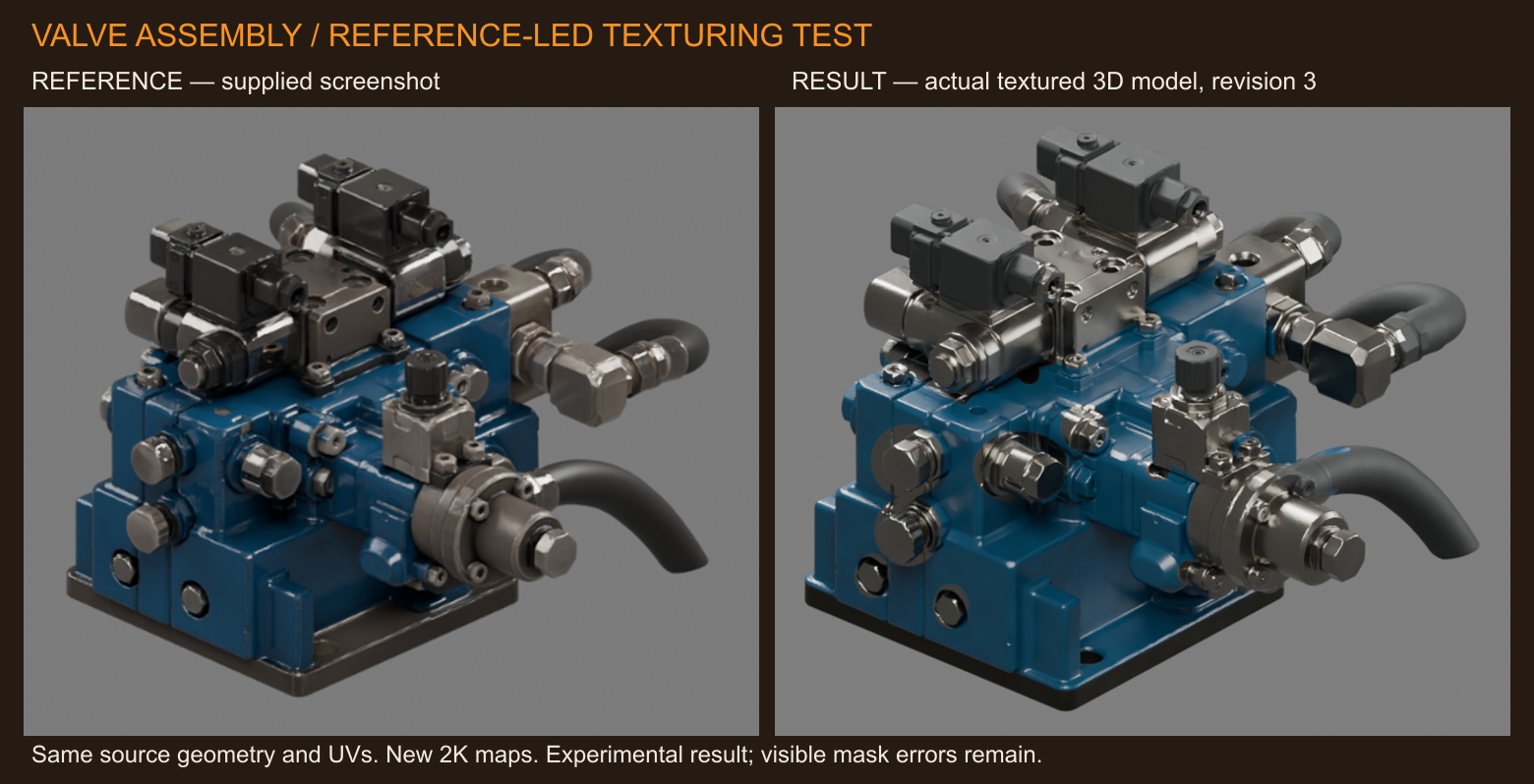
The blue/steel/black material separation gives a recognizable match from the reference side. Existing geometry, normals, UVs, nodes and triangle count are preserved. Three standalone 2K maps are embedded in the new GLB and available separately.
What went poorly
I flipped the UVs in the first pass. Correcting that fixed the scattered materials, but approximate masks still leave spill on hose collars and fittings. The finish is too clean and evenly polished; the inferred rear is weaker than the front.
Inspect the Actual 3D Model
Drag to orbit. Scroll or pinch to zoom. Before/after uses the same geometry, camera and browser lighting.
Loading actual GLB…
One fused mesh; there are no independently isolated components. Browser lighting differs from the Cycles stills and the unknown reference lighting. No baked AO is applied. Micro-normal detail is synthetic and deliberately weak.
What “no cheating” means here
Only the supplied stripped ForgeMedia GLB and the screenshot were used as asset inputs. No original textured GLB, original atlas, extracted original materials, new generated geometry, or image-generated imitation of a successful result was used. The screenshot informed hand-authored material labels and color choices; its lighting and pixels were not projected onto the model.
All reference-independent work ran locally; no paid texture-generation API was called. The source GLB SHA-256 is 6bd2922c4449228169d1486614956f58ec5a2ef382f2f59e68bb912a602f2f90. Its original binary buffer remains an exact byte-for-byte prefix of the derivative. Scope: the entire sole mesh’s material maps; no remeshing, UV edits or mesh splitting.
Procedure followed: Blender → texturing-workflow. The per-object isolation step reduces to the whole single mesh. Raster UV testing does not prove subpixel non-overlap. The requested final goal was not fully reached: this is a documented partial visual match, with no artist approval or target-engine validation.
The Ten-Step Walkthrough
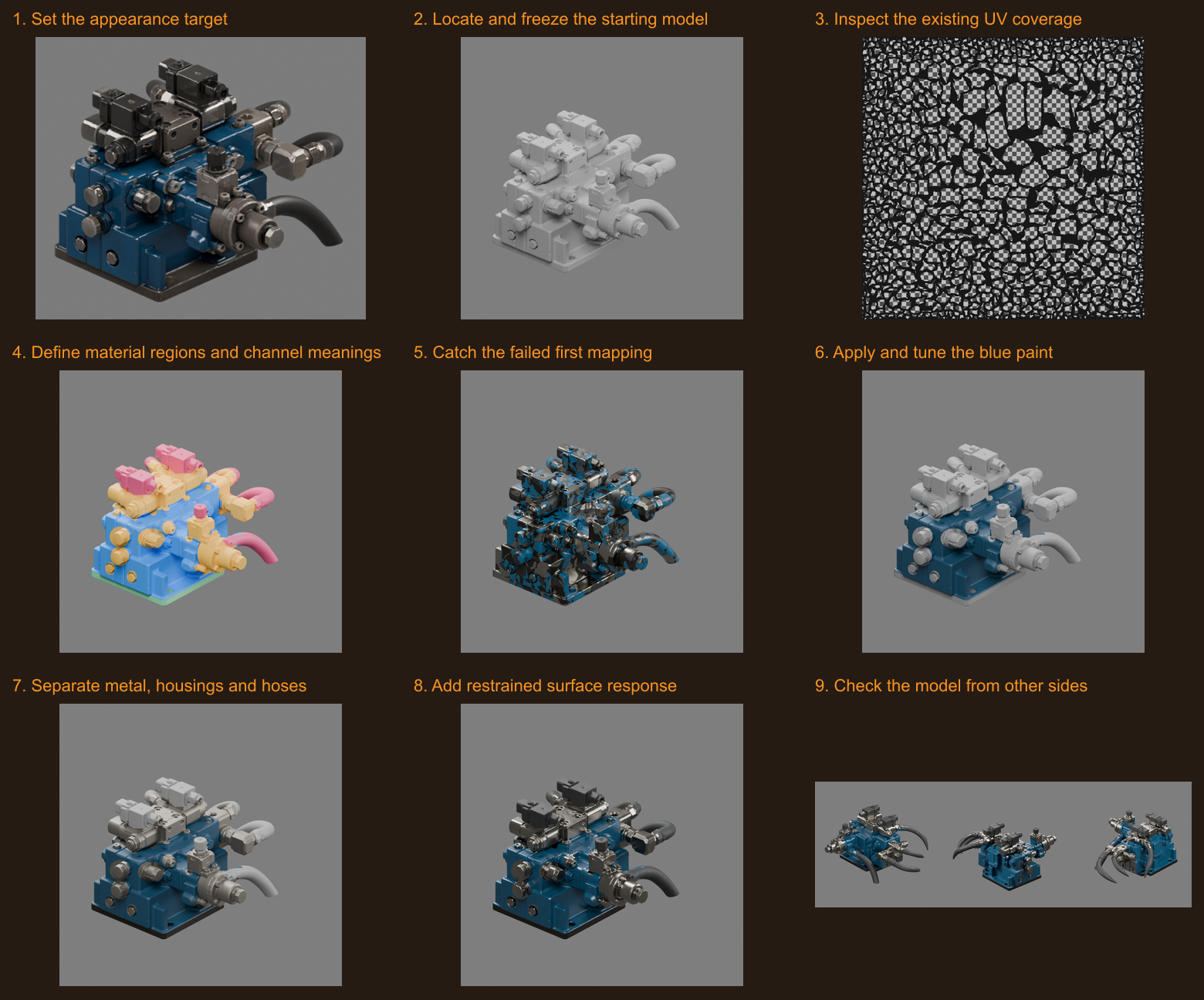
These are genuine source, diagnostic and render images. Click any image to inspect its full resolution. Corrected stages are shown together for comparison; the rejected first render is retained in step 5.
01
Set the appearance target
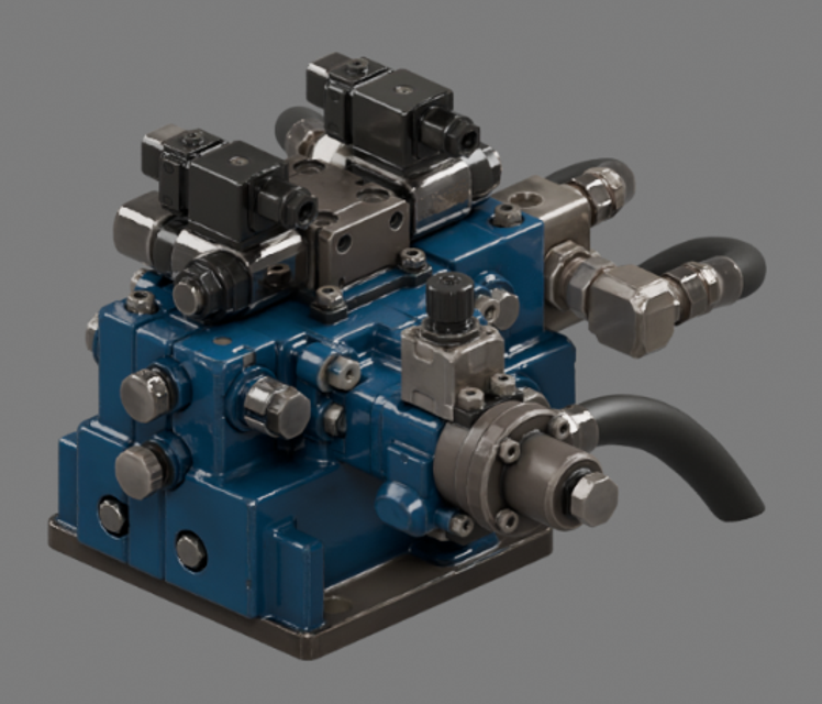
Used only the left side of Adam’s supplied screenshot: dark blue painted castings, exposed steel hardware, black electrical housings and rubber hoses. The screenshot was inspected, not copied into the texture atlas. The original textured asset and its maps were not accessed.
01-reference.png
02
Locate and freeze the starting model
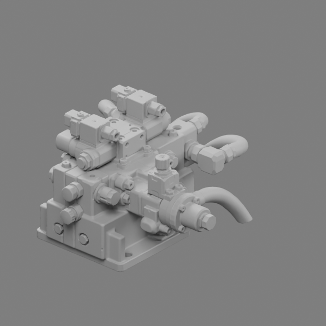
Downloaded the exact ForgeMedia record supplied in the request. Inspected one fused mesh, 262,044 vertices, 456,645 triangles, one UV set and zero texture images. Preserved the source GLB byte-for-byte; all edits are separate derivatives.
02-baseline.png
03
Inspect the existing UV coverage
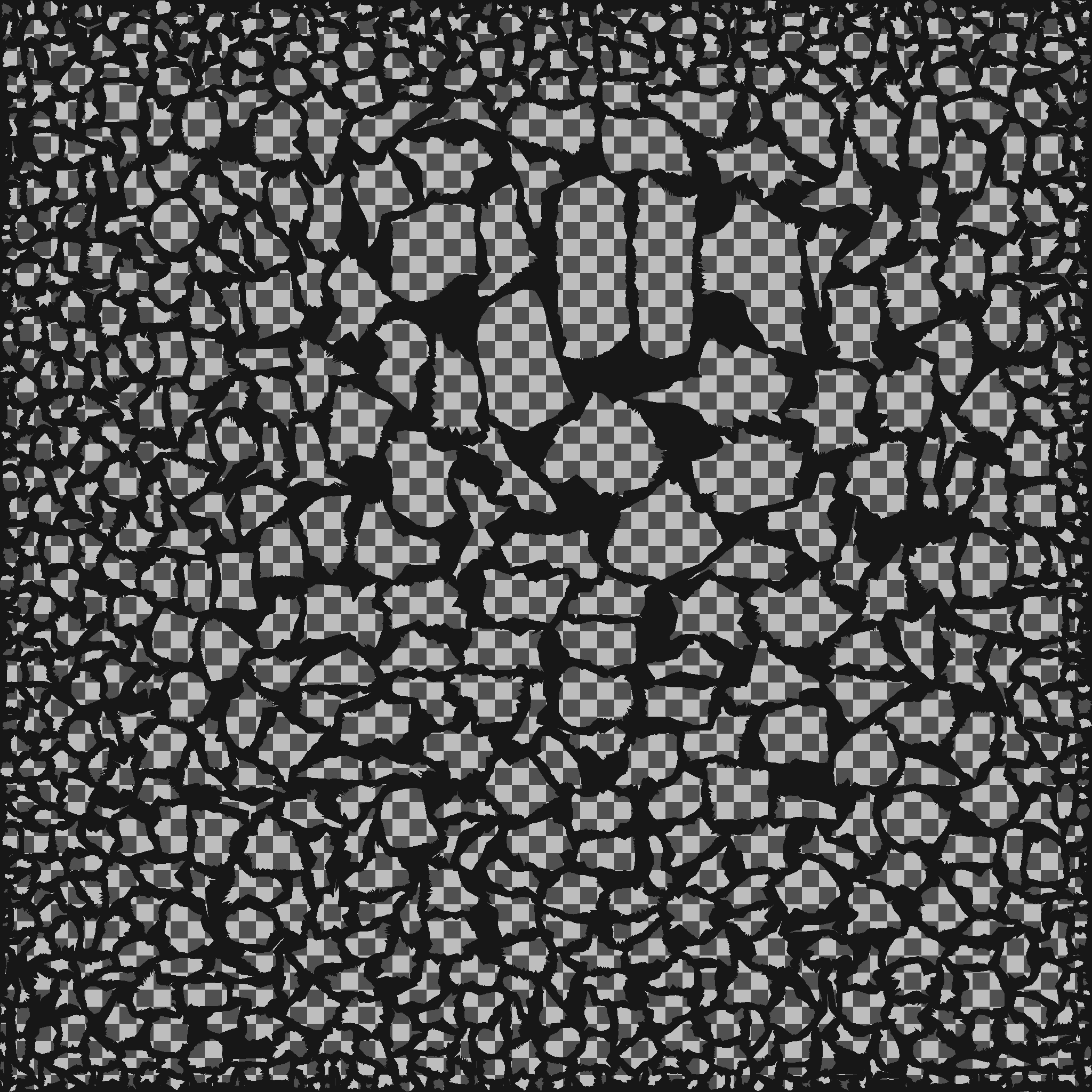
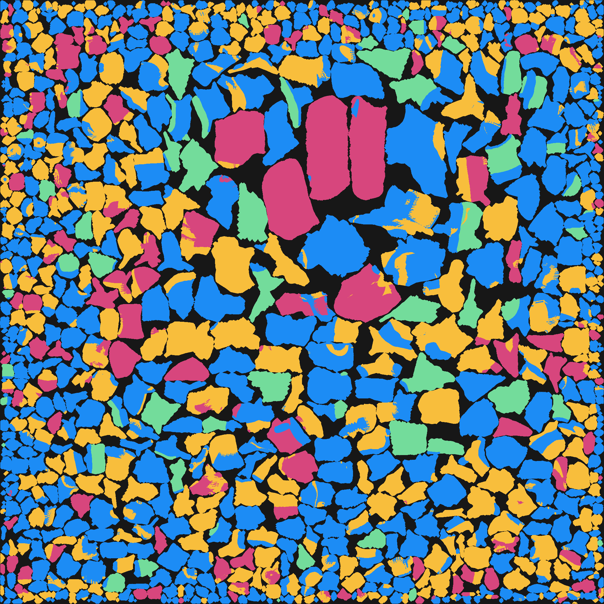
Rasterized the original UV triangles at 2048 × 2048. Found 2,176,582 covered texels and zero conflicting raster samples with a 0.005 model-unit tolerance. This is a raster check, not a mathematical proof of no subpixel overlap. The entire single mesh is in scope; there are no protected neighboring objects.
uv-coverage.png
04
Define material regions and channel meanings
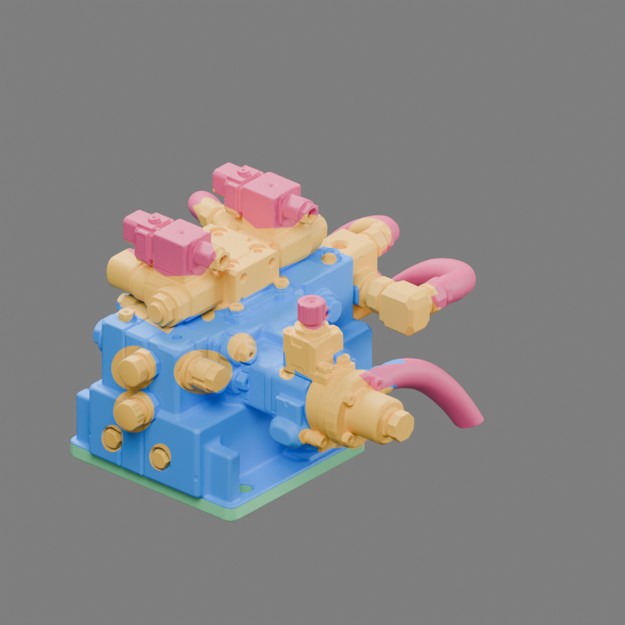
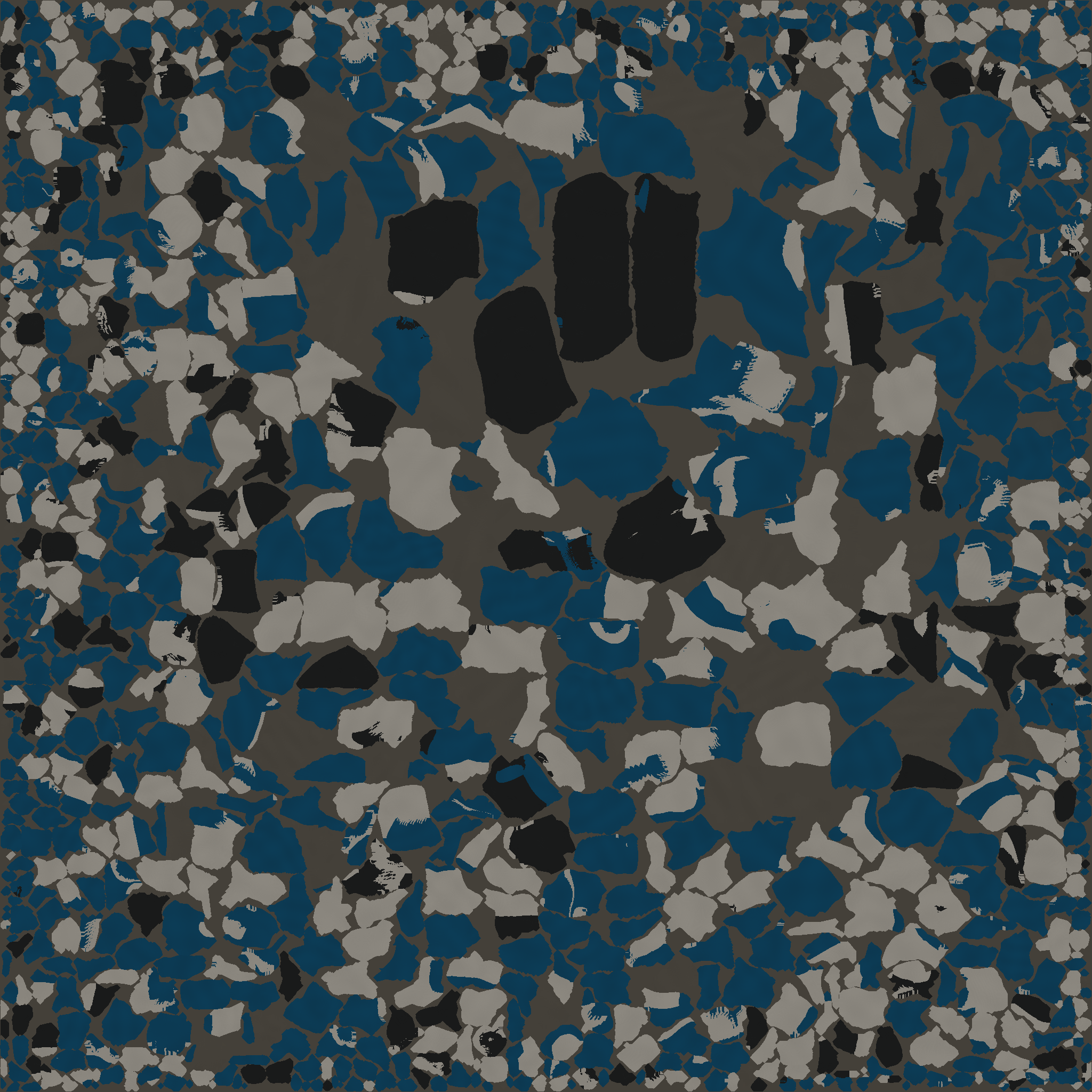
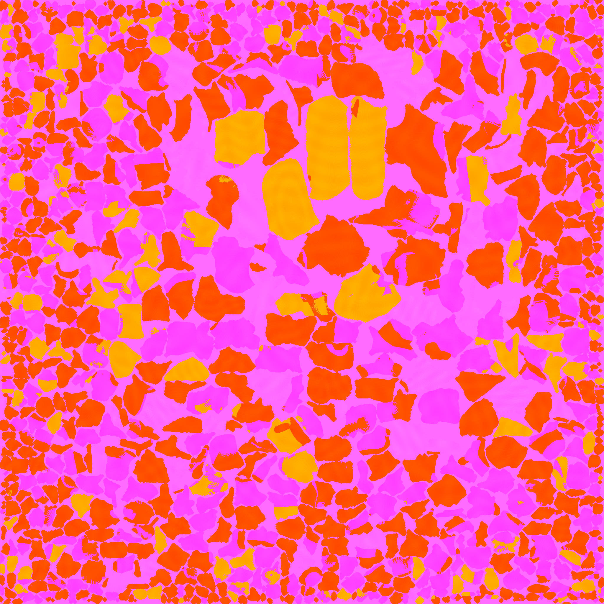
Built masks from 3D positions and manually outlined visible parts. Blue = paint; gold = steel; pink = rubber/polymer; green = base steel. These are approximate part boundaries on a fused mesh, not pre-existing component IDs. Base color is sRGB; packed G is roughness and B is metallic. R stays white and is not connected as AO.
04-mask.pngmaterial-mask.png
05
Catch the failed first mapping
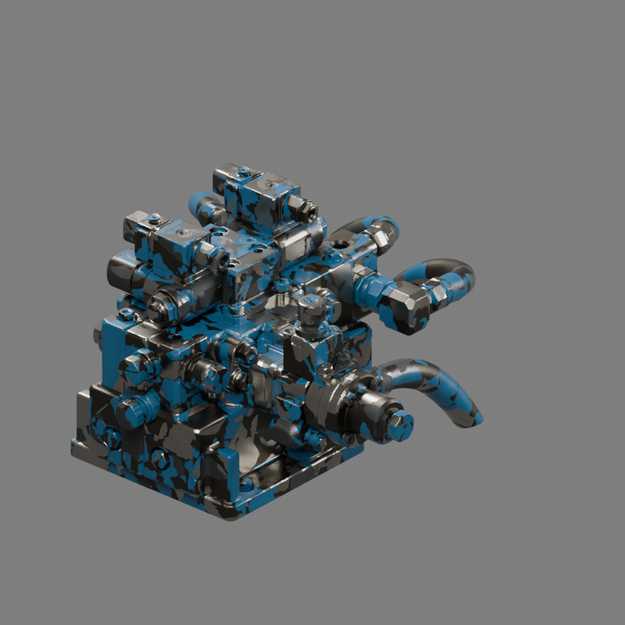
This genuinely happened: I incorrectly flipped the glTF V coordinate, scattering paint and metal across the wrong islands. Visual inspection rejected the pass. The corrected rasterizer writes glTF’s image-down UV coordinates directly to PNG rows. The failed render is retained here rather than hidden.
rejected-v1/08-pbr.png
06
Apply and tune the blue paint
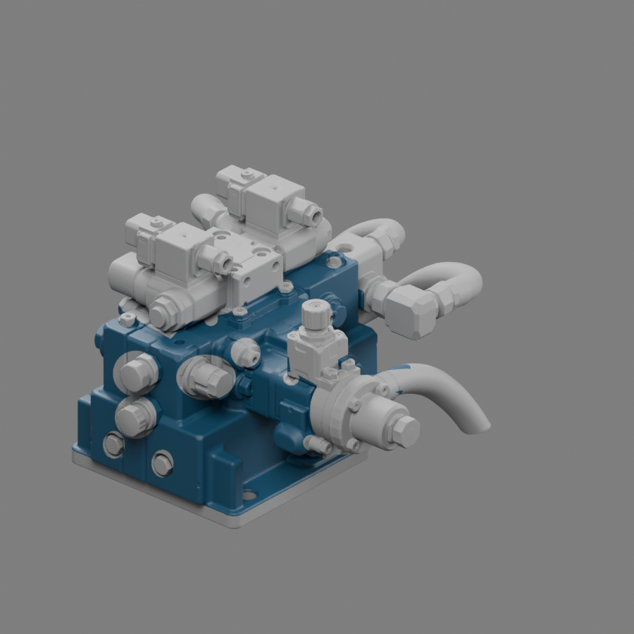
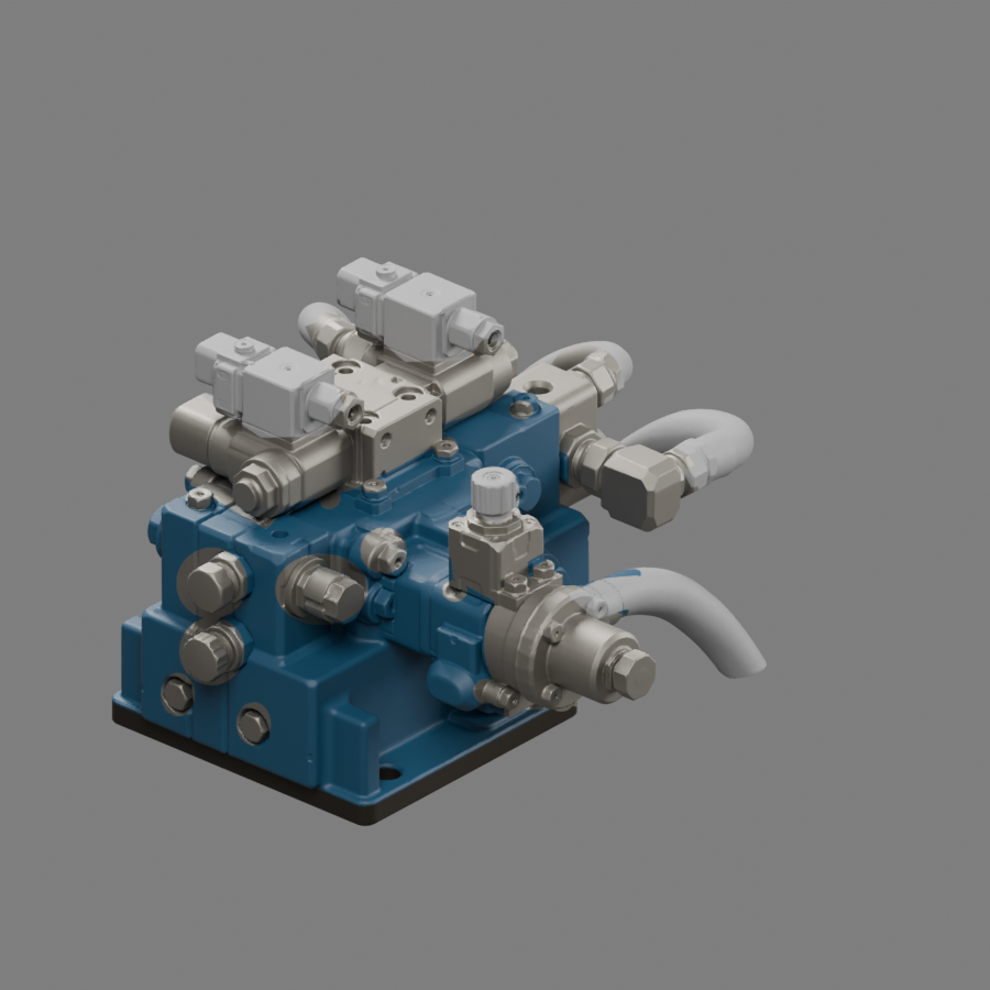
Applied newly authored blue base color only to the paint mask. The other regions are neutral in this diagnostic stage. Darkened the first corrected blue after reference comparison. No new geometry, UV unwrapping, material-slot splitting or original texture recovery was used.
05-paint.png
07
Separate metal, housings and hoses
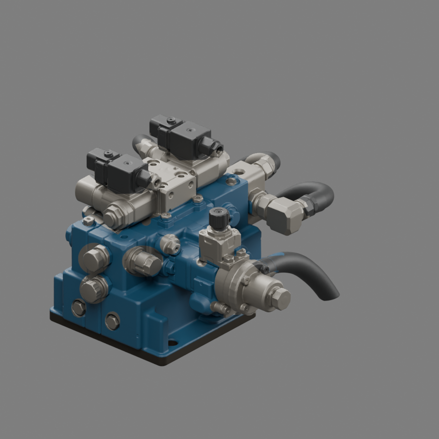
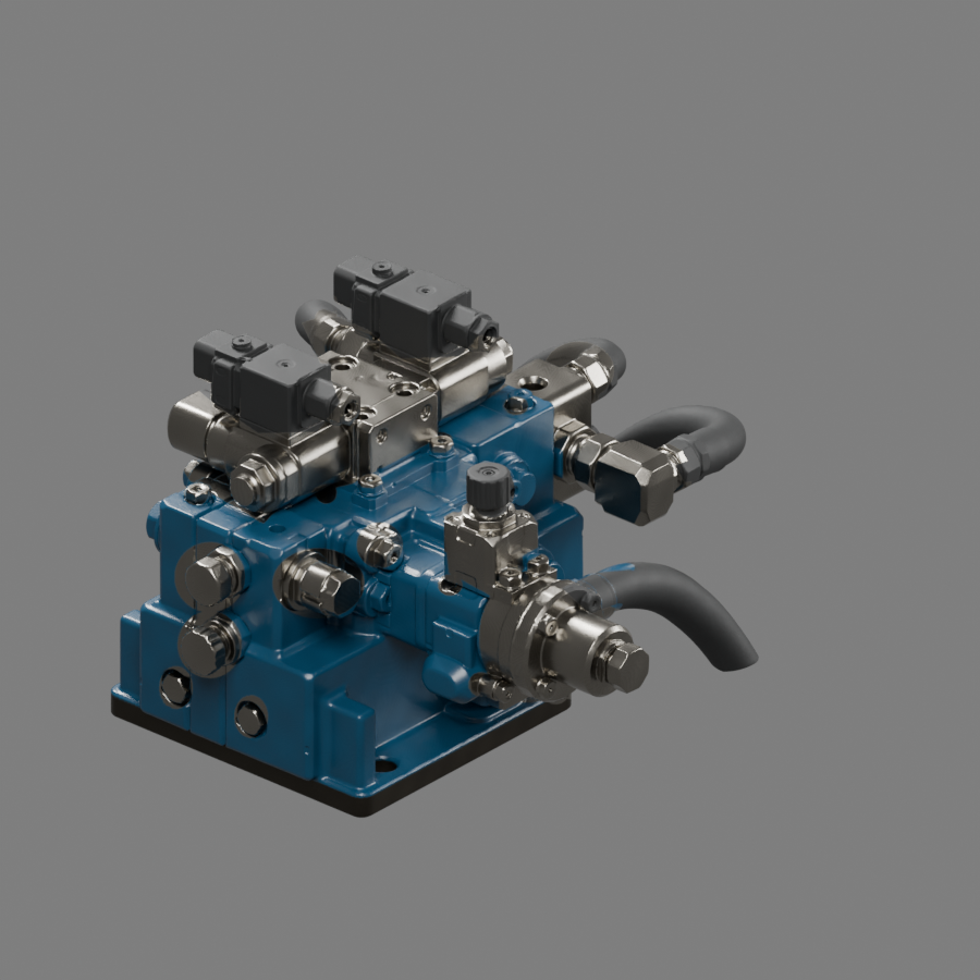
Added steel-colored surfaces and metallic response to the fittings, then dark dielectric housings and rubber hoses. The two images isolate those successive changes. Refined an overly broad metal mask on the front casting and removed most blue contamination from the hoses. Some boundary spill and painted fittings remain.
06-metal.png07-rubber.png
08
Add restrained surface response
Added subtle color and roughness variation plus a very weak synthetic tangent-space micro-normal. Paint and rubber remain nonmetallic. Did not invent heavy scratches or copy baked highlights from the reference. The result is cleaner and smoother than the reference, and the steel is still too uniformly polished.
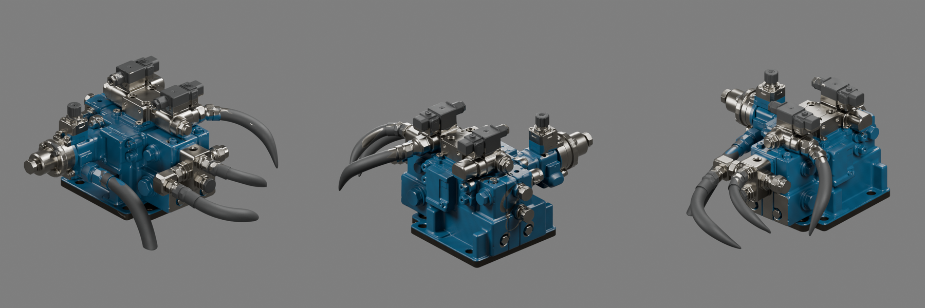
Rendered three additional orbit angles. These expose the weak point: the rear has no supplied reference and its material boundaries are inferred. Hose collars, several bolts and hidden fittings still have imperfect assignments. Keeping these views prevents the attractive front view from standing in for all-around quality.
09-orbit.png
10
Compare and package the actual result
The left image is the supplied reference; the right is a Cycles render of the newly textured source mesh. Crops normalize subject size, but the reference camera and lighting are only approximated. Exported a separate GLB with three embedded 2K maps and verified original geometry-buffer bytes, mesh definitions, nodes and UV accessors are unchanged. This is an experimental result, not an approved material match.
10-comparison.png
My Assessment
The workflow protected the source well and made the failures visible. It did not magically identify engineering parts inside a fused mesh. The broad appearance is convincing enough for a texturing exercise, but close inspection still catches incorrect material boundaries, missing wear and inconsistent hardware assignments. I would not call this a faithful production match.
The highest-value improvement is to correct the material masks around each fitting and hose in multiple views, then tune steel roughness and restrained edge wear against additional reference views. More generic noise would not solve those errors.